Introduction
Estimating edge protection quantities from construction drawings is not simply a matter of measuring the building perimeter.
Different floors, openings, corners, fixing conditions, and construction stages can all change the final quantity. A useful takeoff needs to connect what is shown on the drawing with how the edge protection system will actually be installed and moved on site.
This guide explains a practical process for estimating barriers, posts, and attachments before preparing the final project BOM.
What Drawings Do You Need for an Edge Protection Takeoff?
A good takeoff usually starts with more than one drawing.
Architectural floor plans are useful for understanding the overall layout, including balconies, terraces, stairs, and floor openings. Structural drawings provide more detail about slab edges, slab thicknesses, beams, structural openings, and possible fixing substrates.
Sections and elevations can help identify level changes, parapets, roof edges and floor-to-soffit conditions that may not be obvious from a plan view.
Where available, formwork drawings and construction sequence information are also valuable because they show how the structure will actually be built.
This matters because a finished architectural drawing does not always show all the temporary fall hazards that will exist during construction.
HSE guidance recommends preventing falls where work at height cannot be avoided and gives priority to collective protection measures that protect everyone at risk. That makes identifying exposed edges and openings an important part of planning temporary protection.
Step 1 — Identify Every Area That Requires Temporary Protection
Do not start by measuring the whole building perimeter.
First identify every location where temporary edge protection may be required during the construction stage you are estimating.
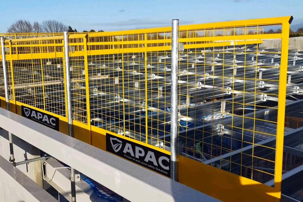
Typical areas include external slab edges, balconies, floor openings, lift shafts, stair edges, formwork edges, roof edges and temporary loading or access openings.
A practical way to review drawings is to mark edges in three categories:
Protection required — exposed edges that need temporary protection.
Already protected — areas where an existing wall, suitable permanent barrier or another approved protection method is already in place.
Needs confirmation — areas where the construction sequence or structural condition is not yet clear.
This prevents the common mistake of treating every line on the architectural perimeter as temporary edge protection.
Step 2 — Divide the Drawing Into Protection Zones
Once the exposed edges are identified, divide them into individual protection zones.
For example:
Zone A — North slab perimeter
Zone B — South balcony edge
Zone C — Stair opening
Zone D — Lift shaft
This step is important because two separate 10 m protection runs are not necessarily equivalent to one continuous 20 m run.
Each independent run can require its own starting post, ending post, attachments and special treatment.
Corners, openings and access gates can change the layout again.
For quantity estimation, it is therefore usually better to calculate each zone separately and combine the results afterwards.
Step 3 — Calculate the Effective Protection Length
Now measure the actual exposed edge that requires temporary protection.
A useful definition is:
Effective Protection Length = Total exposed edge requiring temporary protection within the selected zone
For example:
North slab edge = 26 m
South slab edge = 18 m
Balcony edge = 8 m
Opening perimeter = 6 m
The total effective protection length would be:
26 + 18 + 8 + 6 = 58 m
However, these four areas should not automatically be treated as one continuous 58 m run.
The 6 m opening, for example, may contain several sides and corners. The balcony may use a different fixing arrangement from the main slab perimeter.
Keep the zone breakdown even after calculating the total length.
Step 4 — Choose the Fixing Method

Before estimating attachments, identify how the system is likely to connect to the structure.
For concrete structures, possible methods may include slab grabs, bolt-down socket bases, compression posts or formwork attachments.
For steel structures, the system may use beam clamps or dedicated steel brackets.
The fixing method matters because attachment quantities follow the post layout and structural condition—not simply the total edge length.
For example, a slab grab clamps onto an accessible concrete slab edge, while a bolt-down system uses a mechanically anchored fixing point. The same 20 m protection line could therefore have similar barrier requirements but very different installation processes.
If you are deciding between concrete fixing methods, see Slab Grab vs Bolt-Down Edge Protection: 7 Factors to Compare Before Choosing.
Step 5 — Estimate the Number of Barriers
If you want to calculate the takeoff manually, start with the barriers.
For a simple protection run:
Barrier Quantity = Effective Edge Length ÷ Barrier Length
Always round up to a whole barrier for the initial estimate.
For example:
Effective edge length = 18 m
Barrier length = 2.6 m
18 ÷ 2.6 = 6.92
Initial estimate:
7 barriers
This is still only a preliminary quantity.
The final arrangement may change if the remaining section is too short for a standard barrier, if shorter barrier sizes are available, or if the run contains corners, gates or other interruptions.
Step 6 — Calculate Posts Separately from Barrier Quantity
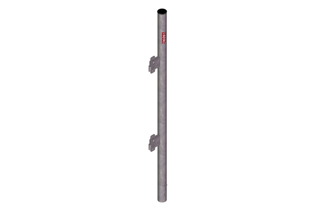
One of the most common takeoff mistakes is assuming that barrier length and maximum post spacing are always the same.
They are not necessarily the same value.
If the selected system has a maximum permitted post spacing, the post layout should be checked independently.
For a simple straight run, an initial spacing-based calculation can be:
Number of Spans = Effective Edge Length ÷ Maximum Post Spacing
Round the number of spans up, then:
Estimated Posts = Number of Spans + 1
For example:
Edge length = 18 m
Maximum post spacing = 2.4 m
18 ÷ 2.4 = 7.5
Round up:
8 spans
Therefore:
Estimated posts = 9
This is different from simply assuming:
7 barriers = 8 posts.
The correct layout depends on the selected barrier, permitted post spacing and tested system configuration.
The manufacturer’s instructions and applicable system documentation should always take priority over a generic calculation.
BSI currently lists BS EN 13374:2025 as the current British Standard for temporary edge protection systems. The standard covers product requirements and test methods for temporary edge protection used during construction and maintenance.
Step 7 — Estimate Attachments from the Post Layout
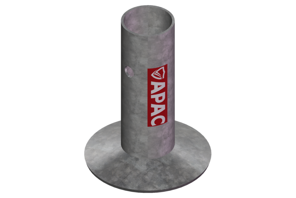
For many edge protection configurations, each post requires a corresponding fixing attachment.
For example:
9 posts
≈ 9 slab grabs or socket bases
But this should not be treated as a universal rule.
A compression post may perform both the post and fixing function. A corner may need a different arrangement. A gate can introduce additional posts. A formwork application may use a completely different connection method.
The better logic is:
Post Layout → Attachment Layout
rather than:
Edge Length → Attachment Quantity
This is another reason the fixing method should be confirmed before the BOM is finalized.
Step 8 — Mark Corners Separately
Corners are easy to underestimate from drawings.
When two protection runs change direction, the system may share a corner post, use two independent posts or require a specific corner arrangement.
The exact solution depends on the edge protection system.
Do not automatically assume:
1 corner = 1 additional post
Instead, mark every corner on the drawing and confirm how the selected system deals with the change in direction.
This becomes particularly important on irregular slab perimeters, balconies and stepped building layouts.
Step 9 — Treat Floor Openings as Independent Protection Zones

Floor openings should normally be treated separately from the main slab perimeter.
Consider a 3 m × 2 m opening.
Its perimeter is:
3 + 2 + 3 + 2 = 10 m
But it is not the same as one straight 10 m edge.
The opening contains four sides and four directional changes. Depending on the system, that can affect the number of barriers, posts and attachments required.
Lift shafts, service openings and large floor voids should therefore be marked as their own protection zones.
This also prevents them from disappearing inside one large total-perimeter calculation.
Step 10 — Account for Construction Stages
For multi-storey construction, quantity estimation should reflect the construction sequence.
Imagine a 20-storey building.
It does not necessarily need 20 complete sets of edge protection because the equipment may be moved upward as construction progresses.
Instead, distinguish between:
Total Construction Stages — the total number of stages or floors through which the system will move.
Stages Active Together — the number of stages that require protection at the same time.
For example:
Total construction stages = 20
Stages active together = 3
If each active floor has approximately the same layout, the working stock may be closer to:
Quantity per floor × 3 active floors
rather than:
Quantity per floor × 20 floors
The actual result should also consider removal delays, changes in floor layout, transfer time and areas that remain protected after work moves upward.
This is why construction stages affect required inventory even though they do not change the geometric edge length shown on the drawing.
Step 11 — Add a Spare Allowance
Construction conditions rarely remain exactly as planned.
Components may be damaged, lost, temporarily retained on another floor or needed for an unexpected layout change.
A spare allowance can therefore be added to the calculated working quantity.
A simple formula is:
Final Estimated Quantity = Working Quantity × (1 + Spare Percentage)
For example:
Working quantity = 100 barriers
Spare allowance = 5%
100 × 1.05 = 105 barriers
There is no universal spare percentage for every project.
The appropriate allowance depends on factors such as project duration, number of reuse cycles, site control, system type and how quickly replacement components can be supplied.
Example: Turning a Drawing Into an Initial Takeoff
Consider two independent protection zones.
Zone A
Effective edge length: 26 m
Barrier length: 2.6 m
Maximum post spacing: 2.6 m
Barrier quantity:
26 ÷ 2.6 = 10 barriers
For a simple continuous run:
10 spans → approximately 11 posts
If one attachment is required per post:
11 attachments
Zone B
Effective edge length: 11 m
Barrier length: 2.6 m
Barrier quantity:
11 ÷ 2.6 = 4.23
Round up:
5 barriers
For a simple layout, the initial estimate may require approximately:
6 posts
6 attachments
Initial Quantity Per Active Stage
Barriers:
10 + 5 = 15
Posts:
11 + 6 = 17
Attachments:
11 + 6 = 17
If three identical stages need to remain protected at the same time:
Barriers:
15 × 3 = 45
Posts:
17 × 3 = 51
Attachments:
17 × 3 = 51
With a 5% spare allowance, rounded up:
48 barriers
54 posts
54 attachments
This is still an initial takeoff. Corners, openings, gates, fixing details and actual system spacing must be checked before issuing the final BOM.
Turn the Takeoff Into a BOM
A useful takeoff should eventually become more than three total numbers.
Create a zone-based schedule showing:
| Zone | Edge Length | Barriers | Posts | Attachments | Fixing Method | Notes |
| Zone A | 26 m | 10 | 11 | 11 | Slab Grab | Straight run |
| Zone B | 11 m | 5 | 6 | 6 | Bolt-Down | Independent edge |
| Opening 1 | Confirm | Confirm | Confirm | Confirm | TBD | Check four corners |
This format makes it easier for the estimator, supplier and site team to understand where each quantity comes from.
It also makes revisions easier when the drawings change.
Common Edge Protection Takeoff Mistakes
Many quantity errors come from a few recurring assumptions.
Using the entire building perimeter without checking whether every edge is exposed can overestimate quantities. Treating several independent edges as one continuous line can underestimate posts and attachments.
Other common problems include ignoring floor openings and corners, assuming barrier length equals maximum post spacing, using one fixing method across different structural conditions, multiplying the quantity by every floor instead of considering active stages, and forgetting spare components.
The best way to reduce these errors is to keep the takeoff zone-based until the final BOM is prepared.
What to Send a Supplier for a More Accurate Estimate
If you want a supplier to review the quantity or prepare a more detailed BOM, provide more than the total edge length.
Useful information includes the architectural floor plan, structural plan, sections, slab thickness, marked active edges, openings and stairs, number of floors, expected construction cycle, preferred fixing method if known, applicable standard and delivery destination.
With this information, the supplier can review the takeoff, identify different fixing conditions and help confirm whether the preliminary quantity reflects the actual installation layout.
For more information on choosing attachments for concrete structures, see Concrete Edge Protection Systems.
Conclusion
Estimating edge protection quantities from construction drawings is not simply a measurement exercise.
The drawings first need to be interpreted in terms of exposed edges, individual protection zones, fixing conditions, openings, corners and construction stages. Only then can barrier, post and attachment quantities be estimated with confidence.
A good takeoff connects the drawing to the way the system will actually be installed, moved and reused on site.
FAQ
How do you calculate edge protection quantities from construction drawings?
Start by identifying all exposed edges that require temporary protection and divide them into individual zones. Measure the effective edge length for each zone, determine the fixing method, and then calculate barriers, posts and attachments according to the selected system layout.
Should I use the entire building perimeter?
No. Only edges that actually require temporary protection during the relevant construction stage should be included. Permanent walls, completed parapets or areas protected by another system should not automatically be counted.
How do I calculate the number of edge protection barriers?
For an initial estimate, divide the effective edge length of each protection zone by the barrier length and round up. Corners, openings, gates and short end sections may change the final arrangement.
How many posts are needed for edge protection?
Posts should be calculated from the actual layout and maximum permitted spacing rather than simply from total edge length. For a simple continuous run, the number of spans plus one can provide an initial estimate, but system requirements should always be checked.
How should floor openings be included in the takeoff?
Treat substantial floor openings and lift shafts as independent protection zones. Calculate each side and mark the corners because an opening is not equivalent to one straight protection run of the same total length.
Do I need edge protection for every floor of a multi-storey building?
Every exposed area that requires protection must be controlled, but you may not need a complete new set of equipment for every floor. If the system is reused as construction progresses, the required inventory depends largely on how many floors or stages need protection at the same time.